Design a Digital Clock Using 8085 Microprocessor
Program to simulate a real-time clock in 8085 Microprocessor
Here we will see one interesting problem. We will see how to simulate one real-time clock using 8085 microprocessor.
Problem Statement−
Write an 8085 Assembly language program to simulate real-time clock.
Discussion−
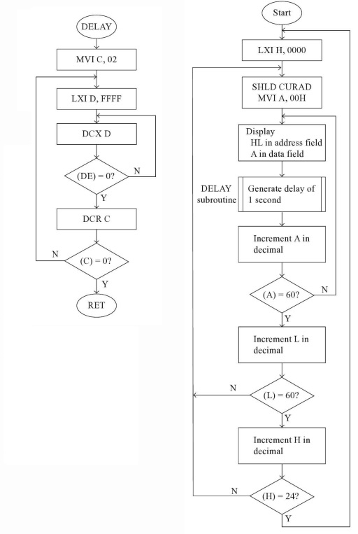
In this program we are creating a real time clock using 8085MPU. Here we are generating 1s delay to update seconds. This clock is 24Hrs clock. We are initializing the clock from 00:00:00. To display the values into 7-segment display we have to use some Port ICs and correct configurations. In each 60 seconds the minute field is updated, and in each 60 minutes the hour field is updated. For decimal update, DAA instruction is used in each increment.
We are storing the hour field into 8008H and minute field is stored at 8007H. The second value is stored at location 8009H.
Note: Here for simplicity we are storing the numbers into memory. To show the numbers, we can use 7 – segment display and other display function for showing it into the display.
Input
Here we are not providing any input.
Flow Diagram

Program
| Address | HEX Codes | Labels | Mnemonics | Comments |
|---|---|---|---|---|
| F000 | 21, 00, 00 | BEG | LXI H,0000H | Clear HL with 0000H |
| F003 | 22, 07, 80 | HR_MIN | SHLD 8007H | Store HL content at 8007H and 8006H |
| F006 | AF | XRA A | Clear A register | |
| F007 | 32, 09, 80 | N_SEC | STA 8009H | Store acc content at 8009H |
| F00A | CD, 34, F0 | CALL DELAY | Delay for 1 second | |
| F00D | 3A, 09, 80 | LDA 8009H | Load the second value | |
| F010 | C6, 01 | ADI 01H | Add 01 with Acc | |
| F012 | 27 | DAA | Adjust decimal | |
| F013 | FE, 60 | CPI 60H | Compare with 60H | |
| F015 | C2, 07, F0 | JNZ N_SEC | If Z = 0, jump to N_SEC | |
| F018 | 2A, 07, 80 | LHLD 8007H | Load HL from 8007H | |
| F01B | 7D | MOV A,L | Load L to A | |
| F01C | C6, 01 | ADI 01H | Add 01 with A | |
| F01E | 27 | DAA | Decimal adjust | |
| F01F | 6F | MOV L,A | Load L from A | |
| F020 | FE, 60 | CPI 60H | Compare A with 60H | |
| F022 | C2, 03, F0 | JNZ HR_MIN | If Z = 0, jump to HR_MIN | |
| F025 | 2E, 00 | MVI L,00H | Clear L register | |
| F027 | 7C | MOV A,H | Load H to A | |
| F028 | C6, 01 | ADI 01H | Add 01 with A | |
| F02A | 27 | DAA | Decimal adjust | |
| F02B | 67 | MOV H,A | Send back A to H | |
| F02C | FE, 24 | CPI 24H | Compare Hour with 24 | |
| F02E | C2, 03, F0 | JNZ HR_MIN | Jump to HR_MIN if Z = 0 | |
| F031 | C3, 00 | JMP BEG | Jump to Begin | |
| F034 | 0E, 02 | DELAY | MVI C,02H | Initialize Count to 02H |
| F036 | 11, FF, FF | L1 | LXI D,FFFFH | Load DE with FFFFH |
| F039 | 1B | L2 | DCX D | Decrease DE |
| F03A | 7A | MOV A,D | Take D to A | |
| F03B | B3 | ORA E | OR A and E | |
| F03C | C2, 16, F0 | JNZ L2 | If Z = 0, jump to L2 | |
| F03F | 0D | DCR C | Decrease C by 1 | |
| F040 | C2, 13, F0 | JNZ L1 | Jump to L1, if Z = 0 | |
| F043 | C9 | RET | Return from subroutine |
Output
The numbers are storing into memory location 8008H – 8007H and 8009H.

Published on 04-Oct-2019 12:49:24
- Related Questions & Answers
- 8085 Program to simulate a real-time clock
- Program to simulate decimal down counter in 8085 Microprocessor
- Real Time Clock (RTC) with Arduino
- Simulate decimal up counter in 8085 Microprocessor
- 8085 Program to simulate decimal up counter
- 8085 Program to simulate decimal down counter
- Program to compute LCM in 8085 Microprocessor
- Program counter (PC) in 8085 Microprocessor
- Program for simulating a stopwatch in 8085 Microprocessor
- Earliest data output time considering TACC in 8085 Microprocessor
- Earliest data output time considering TCE in 8085 Microprocessor
- Earliest data output time considering TOE in 8085 Microprocessor
- C program to print digital clock with current time
- Program to perform linear search in 8085 Microprocessor
- Program to check for palindrome in 8085 Microprocessor
Design a Digital Clock Using 8085 Microprocessor
Source: https://www.tutorialspoint.com/program-to-simulate-a-real-time-clock-in-8085-microprocessor
0 Response to "Design a Digital Clock Using 8085 Microprocessor"
Post a Comment